- 您现在的位置:买卖IC网 > Sheet目录1168 > 71M6513H-DB (Maxim Integrated Products)BOARD DEMO 71M6513H ENERGY METER
�� �
�
�71M6513/71M6513H� Demo� Board� User’s� Manual�
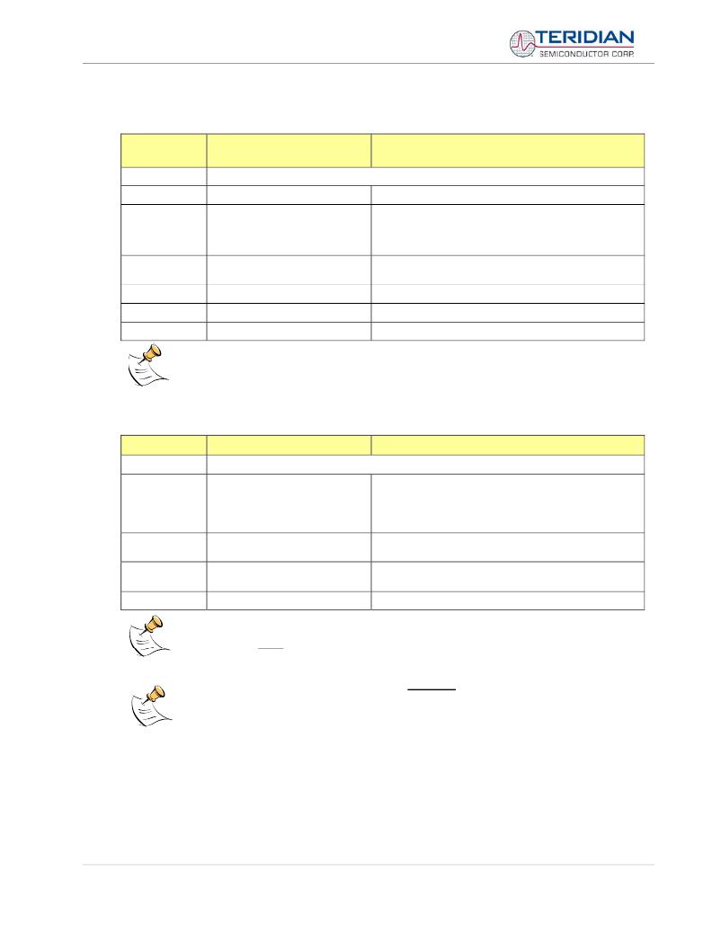
�Commands� controlling� the� Auto-Calibration� Function:�
�CL�
�Description:�
�Usage:�
�AUTO-CALIBRATION�
�CONTROL�
�Allows� the� user� to� initiate� auto-calibration� and� to� store� calibration� values.�
�CL� [option]�
�Command�
�combinations:�
�Example:�
�CLB�
�CLS�
�CLR�
�CLD�
�CLB�
�Begin� auto-calibration.� Prior� to� auto-calibration,� the� calibration�
�coefficients� are� automatically� restored� from� flash� memory.� If�
�the� coefficients� are� not� unity� gain� (0x4000),� auto-calibration�
�will� yield� poor� results.�
�Save� calibration� coefficients� to� EEPROM� starting� at� address�
�0x0004�
�Restore� calibration� coefficients� from� EEPROM�
�Restore� coefficients� from� flash� memory�
�Starts� auto-calibration�
�Before� starting� the� auto-calibration� process,� target� values� for� voltage� and� current� must� be� entered� in� I/O� RAM�
�prior� to� calibration� (V� at� 0x2029,� I� at� 0x202A,� duration� in� accumulation� intervals� at� 0x2028),� and� the� target� voltage�
�and� current� must� be� applied� constantly� during� calibration.� No� phase� adjustment� will� be� performed.� Coefficients�
�can� be� saved� to� EEPROM� using� the� CLS� command.�
�Commands� controlling� the� Pulse� Counter� Function� (Demo� Code� Revision� 3.05� only)�
�CP�
�Description:�
�Usage:�
�PULSE-COUNT� CONTROL�
�Allows� the� user� to� control� the� pulse� count� functions.�
�CP� [option]�
�Command�
�CPA�
�Start� pulse� counting� for� time� period� defined� with� the� CPD�
�combinations:�
�CPC�
�CPDn�
�command.� Pulse� counts� will� display� with� commands� M15.2,�
�M16.2�
�Clear� the� absolute� pulse� count� displays� (shown� with�
�commands� M15.1,� M16.1)�
�Set� time� window� for� pulse� counters� to� n� seconds,� n� is� inter-�
�preted� as� a� decimal� number.�
�Example:�
�CPD60�
�Set� time� window� to� 60� seconds.�
�Pulse� counts� accumulated� over� a� time� window� defined� by� the� CPD� command� will� be� displayed� by�
�M15.2� or� M16.2� after� the� defined� time� has� expired.�
�Commands� M15.1� and� M16.1� will� display� the� absolute� pulse� count� for� the� W� and� VAR� outputs.�
�These� displays� are� reset� to� zero� with� the� CPC� command� (or� the� XRAM� write� )1=2).�
�Commands� M15.2� and� M16.2� will� display� the� number� of� pulses� counted� during� the� interval� defined�
�by� the� CPD� command.� These� displays� are� reset� only� after� a� new� reading,� as� initiated� by� the� CPA�
�command.�
�Page:� 21� of� 112�
�?� 2005-2006� TERIDIAN� Semiconductor� Corporation�
�Revision� 5.6�
�发布紧急采购,3分钟左右您将得到回复。
相关PDF资料
71M6515H-DB
BOARD DEMO 71M6515H ENERGY METER
71M6521FE-DB
BOARD DEMO FOR 71M6521FE
71M6531F-DB
BOARD DEMO 71M6531F
71M6533-DB
BOARD DEMO 71M6533
71M6534H-DB
BOARD DEMO 71M6534H
71M6541F-DB
DEMO BOARD 71M6541F
71M6543F-DB-CT
DEMO BOARD 71M6543F-DB-CT
72-CNV-5
CONVERTER RS-232 TO RS-422 5V
相关代理商/技术参数
71M6513H-IEL
制造商:未知厂家 制造商全称:未知厂家 功能描述:71M6513
71M6513H-IEL/F
功能描述:计量片上系统 - SoC 3-Phase Energy Meter I/C RoHS:否 制造商:Maxim Integrated 核心:80515 MPU 处理器系列:71M6511 类型:Metering SoC 最大时钟频率:70 Hz 程序存储器大小:64 KB 数据 RAM 大小:7 KB 接口类型:UART 可编程输入/输出端数量:12 片上 ADC: 安装风格:SMD/SMT 封装 / 箱体:LQFP-64 封装:Reel
71M6513H-IELR
功能描述:计量片上系统 - SoC 3-Phase Energy Meter I/C RoHS:否 制造商:Maxim Integrated 核心:80515 MPU 处理器系列:71M6511 类型:Metering SoC 最大时钟频率:70 Hz 程序存储器大小:64 KB 数据 RAM 大小:7 KB 接口类型:UART 可编程输入/输出端数量:12 片上 ADC: 安装风格:SMD/SMT 封装 / 箱体:LQFP-64 封装:Reel
71M6513H-IELR/F
功能描述:计量片上系统 - SoC 3-Phase Energy Meter I/C RoHS:否 制造商:Maxim Integrated 核心:80515 MPU 处理器系列:71M6511 类型:Metering SoC 最大时钟频率:70 Hz 程序存储器大小:64 KB 数据 RAM 大小:7 KB 接口类型:UART 可编程输入/输出端数量:12 片上 ADC: 安装风格:SMD/SMT 封装 / 箱体:LQFP-64 封装:Reel
71M6513H-IGT/F
功能描述:计量片上系统 - SoC 3-Phase Energy Meter I/C RoHS:否 制造商:Maxim Integrated 核心:80515 MPU 处理器系列:71M6511 类型:Metering SoC 最大时钟频率:70 Hz 程序存储器大小:64 KB 数据 RAM 大小:7 KB 接口类型:UART 可编程输入/输出端数量:12 片上 ADC: 安装风格:SMD/SMT 封装 / 箱体:LQFP-64 封装:Reel
71M6513H-IGTR/F
功能描述:计量片上系统 - SoC 3-Phase Energy Meter I/C RoHS:否 制造商:Maxim Integrated 核心:80515 MPU 处理器系列:71M6511 类型:Metering SoC 最大时钟频率:70 Hz 程序存储器大小:64 KB 数据 RAM 大小:7 KB 接口类型:UART 可编程输入/输出端数量:12 片上 ADC: 安装风格:SMD/SMT 封装 / 箱体:LQFP-64 封装:Reel
71M6513H-IGTR/F1
功能描述:计量片上系统 - SoC
RoHS:否 制造商:Maxim Integrated 核心:80515 MPU 处理器系列:71M6511 类型:Metering SoC 最大时钟频率:70 Hz 程序存储器大小:64 KB 数据 RAM 大小:7 KB 接口类型:UART 可编程输入/输出端数量:12 片上 ADC: 安装风格:SMD/SMT 封装 / 箱体:LQFP-64 封装:Reel
71M6513-IEL
制造商:未知厂家 制造商全称:未知厂家 功能描述:71M6513